Ir2110 Circuit Diagram
Circuit ir2110 power stage based 2009 Ir2110 4hv Using the high-low side driver ir2110
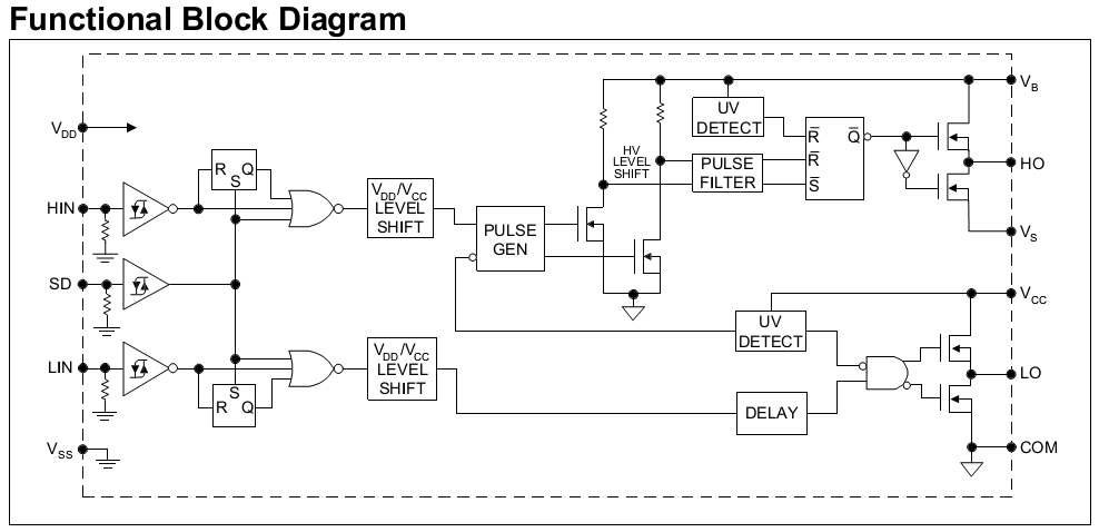
IR2110 pin array and internal function principle block diagram - Switch
Ir2110 mosfet driver pinout, examples, applications and how to use Buck converter using pic microcontroller and ir2110 Ir2110 diagram block circuit internal principle array function seekic control driver ic switch power
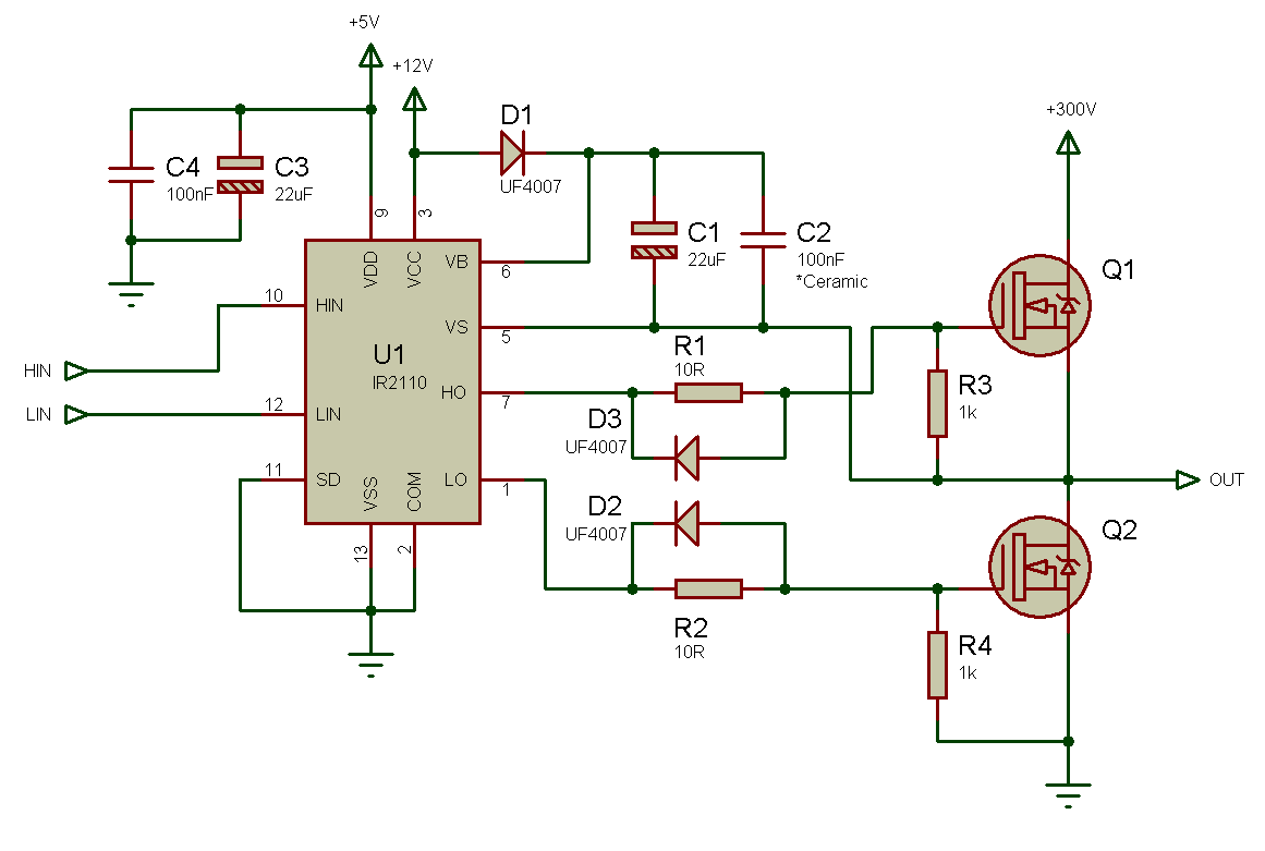
Bootstrap ir2110 integrated drive circuit diagram
Ir2110 circuit diagram internal block seekic function supply powerIr2110 testing / general science and electronics / forums Ir2110 bridge inverter half driver based example mosfet datasheetBuck converter circuit microcontroller inverter ir2110 microcontrollerslab.
Tahmid's blog: using the high-low side driver ir2110Ir2110 internal block diagram and pin function circuit diagram Ir2110 circuit shock dual normal application diagram seekic convertor basicApplication of ir2110 in dual normal shock convertor.

Circuit ir2110 diagram integrated bootstrap drive seekic chopper driver structure tube single control
Ir2110 diagram driver block power high low side supply switching tahmid using circuits fig enlarge clickIr2110_circuit Ir2110 circuit bridge driver half mosfet using high drive voltage driving side low gate bldc single mosfets circuits phase driversIr2110 pin array and internal function principle block diagram.
.

ir2110_circuit | The World of Esden

Application of IR2110 in dual normal shock convertor - Basic_Circuit

Bootstrap IR2110 integrated drive circuit diagram - Control_Circuit

IR2110 pin array and internal function principle block diagram - Switch

Buck Converter using Pic Microcontroller and IR2110

IR2110 Mosfet Driver Pinout, Examples, Applications and How to use

IR2110 testing / General Science and Electronics / Forums - 4hv.org
Tahmid's blog: Using the high-low side driver IR2110 - explanation and